References
Blog posts out there are fragmentary, badly formatted, and sometimes erroneous—I wouldn't recommend using them.
Here's the material from the Modbus Chinese site:
MODBUS Protocol Chinese/English Version Preview and Download | Modbus IoT Cloud Platform
More authoritative is the official documentation:
MODBUS Application Protocol 1 1 b
Other official documents can be found here:
To be honest, I'm not fully satisfied with the official docs either. To preserve their ancient design architecture, the descriptions of the frame fields are no longer intuitive, and there are also a few typos.
Below is the useful information I've rewritten myself.
There's also a library I implemented myself:

Protocol Features
Overall Frame Structure
| Header | Address field | Function code | Data field | Checksum field | |
|---|---|---|---|---|---|
| RTU | 1 byte (Slave ID) | 1 byte | n bytes (variable) | 2 bytes (CRC-MB16 over everything else) | |
| TCP | 6 bytes (2-byte Transaction ID + 2-byte Protocol ID—all zeros + 2-byte total length of following bytes—includes the Slave ID) | 1 byte (Slave ID) | 1 byte | n bytes (variable) |
Regarding the header: in the official model it is classified under the address field, but the total byte length actually includes the Slave ID. Probably because the overall model was already fixed when only the serial protocol existed, and the later Modbus TCP had to be bolted on for compatibility. I've simply reclassified it here. It's not standard, but I'm happy with it.
Register Properties
| RW attribute | Bit width | |
|---|---|---|
| Coils (0x01) | Read/Write | 1 bit |
| Discrete Input Registers (0x02) | Read-only | 1 bit |
| Holding Registers (0x03) | Read/Write | 16 bits |
| Input Registers (0x04) | Read-only | 16 bits |
Overall Model
Think of it as a memory structure abstracted in software: each address stores data with a different meaning—the same idea as an FPGA emulating SRAM. However, not every register address is 16 bits wide; it can also be 1 bit wide. The attributes are RO/RW.
RTU Series
(0x01) Read Coils
Master Request
| Address field | Function code | Starting address | Quantity of coils | Checksum field |
|---|---|---|---|---|
| 1 byte | 1 byte | 2 bytes | 2 bytes | 2 bytes (CRC-MB16) |
Slave Response
| Address field | Function code | Byte count | Coil status | Checksum field |
|---|---|---|---|---|
| 1 byte | 1 byte | 1 byte (byte count of the Coil Status section) | n bytes | 2 bytes (CRC-MB16) |
Example
Request to read coil data at addresses 20–38. In short, the response packs bits from the lowest address upward; if the last byte isn't full, the remaining high-order bits are zero-filled.
The last response byte covers output statuses 38–36, with the remaining 5 bits zero-filled (up to the high-order end).
| Request | Response | ||
|---|---|---|---|
| Address field (Slave ID) | 0x01 | Address field (Slave ID) | 0x01 |
| Function code | 0x01 | Function code | 0x01 |
| Starting address high byte | 0x00 | Byte count | 0x03 |
| Starting address low byte | 0x13 | Output status 27–20 | 0xCD |
| Quantity high byte | 0x00 | Output status 35–28 | 0x6B |
| Quantity low byte | 0x13 | Output status 38–36 | 0x05 |
| CRC low byte | 0xA9 | CRC low byte | 0x42 |
| CRC high byte | 0xC8 | CRC high byte | 0x82 |
(0x02) Read Discrete Input Registers
Master Request
| Address field | Function code | Starting address | Quantity of discrete inputs | Checksum field |
|---|---|---|---|---|
| 1 byte | 1 byte | 2 bytes | 2 bytes | 2 bytes (CRC-MB16) |
Slave Response
| Address field | Function code | Byte count | Discrete input status | Checksum field |
|---|---|---|---|---|
| 1 byte | 1 byte | 1 byte (byte count of the Discrete Input Status section) | n bytes | 2 bytes (CRC-MB16) |
Example
Request to read discrete input data at addresses 197–218. In short, the response packs bits from the lowest address upward; if the last byte isn't full, the remaining high-order bits are zero-filled.
The last response byte covers input statuses 218–213, with the remaining 2 bits zero-filled (up to the high-order end).
| Request | Response | ||
|---|---|---|---|
| Address field (Slave ID) | 0x01 | Address field (Slave ID) | 0x01 |
| Function code | 0x02 | Function code | 0x02 |
| Starting address high byte | 0x00 | Byte count | 0x03 |
| Starting address low byte | 0xC4 | Input status 204–197 | 0xAC |
| Quantity high byte | 0x00 | Input status 212–205 | 0xDB |
| Quantity low byte | 0x16 | Input status 218–213 | 0x35 |
| CRC low byte | 0xB8 | CRC low byte | 0x22 |
| CRC high byte | 0x39 | CRC high byte | 0x88 |
(0x03) Read Holding Registers
Master Request
| Address field | Function code | Starting address | Quantity of holding registers | Checksum field |
|---|---|---|---|---|
| 1 byte | 1 byte | 2 bytes | 2 bytes | 2 bytes (CRC-MB16) |
Slave Response
| Address field | Function code | Byte count | Holding register values | Checksum field |
|---|---|---|---|---|
| 1 byte | 1 byte | 1 byte (byte count of the Holding Register Values section) | n bytes | 2 bytes (CRC-MB16) |
Example
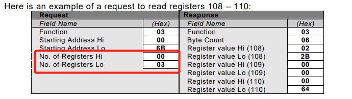
Request to read holding register data at addresses 108–110.
| Request | Response | ||
|---|---|---|---|
| Address field (Slave ID) | 0x01 | Address field (Slave ID) | 0x01 |
| Function code | 0x03 | Function code | 0x03 |
| Starting address high byte | 0x00 | Byte count | 0x06 |
| Starting address low byte | 0x6B | Register value high byte (108) | 0x02 |
| Register quantity high byte | 0x00 | Register value low byte (108) | 0x2B |
| Register quantity low byte | 0x03 | Register value high byte (109) | 0x00 |
| CRC low byte | 0x74 | Register value low byte (109) | 0x00 |
| CRC high byte | 0x17 | Register value high byte (110) | 0x00 |
| Register value low byte (110) | 0x64 | ||
| CRC low byte | 0x05 | ||
| CRC high byte | 0x7A |
(0x04) Read Input Registers
Master Request
| Address field | Function code | Starting address | Quantity of input registers | Checksum field |
|---|---|---|---|---|
| 1 byte | 1 byte | 2 bytes | 2 bytes | 2 bytes (CRC-MB16) |
Slave Response
| Address field | Function code | Byte count | Input register values | Checksum field |
|---|---|---|---|---|
| 1 byte | 1 byte | 1 byte (byte count of the Input Register Values section) | n bytes | 2 bytes (CRC-MB16) |
Example
Request to read input register data at addresses 9–10.
| Request | Response | ||
|---|---|---|---|
| Address field (Slave ID) | 0x01 | Address field (Slave ID) | 0x01 |
| Function code | 0x04 | Function code | 0x04 |
| Starting address high byte | 0x00 | Byte count | 0x06 |
| Starting address low byte | 0x6B | Register value high byte (9) | 0x02 |
| Register quantity high byte | 0x00 | Register value low byte (9) | 0x2B |
| Register quantity low byte | 0x03 | Register value high byte (10) | 0x00 |
| CRC low byte | 0xC1 | Register value low byte (10) | 0x00 |
| CRC high byte | 0xD7 | CRC low byte | 0xF3 |
| CRC high byte | 0xF4 |
(0x05) Write Single Coil
For writing a single coil, the output value field only allows FF 00 for ON and 00 00 for OFF; any other value is invalid.
Master Request
| Address field | Function code | Output address | Output value | Checksum field |
|---|---|---|---|---|
| 1 byte | 1 byte | 2 bytes | 2 bytes | 2 bytes (CRC-MB16) |
Slave Response
| Address field | Function code | Address | Output value | Checksum field |
|---|---|---|---|---|
| 1 byte | 1 byte | 2 bytes | 2 bytes | 2 bytes (CRC-MB16) |
Example
Write the coil at address 173 to ON.
| Request | Response | ||
|---|---|---|---|
| Address field (Slave ID) | 0x01 | Address field (Slave ID) | 0x01 |
| Function code | 0x05 | Function code | 0x05 |
| Register address high byte | 0x00 | Register address high byte | 0x00 |
| Register address low byte | 0xAC | Register address low byte | 0xAC |
| Register value high byte | 0xFF | Register value high byte | 0xFF |
| Register value low byte | 0x00 | Register value low byte | 0x00 |
| CRC low byte | 0x4C | CRC low byte | 0x4C |
| CRC high byte | 0x1B | CRC high byte | 0x1B |
(0x06) Write Single Holding Register
Master Request
| Address field | Function code | Holding register address | Register value | Checksum field |
|---|---|---|---|---|
| 1 byte | 1 byte | 2 bytes | 2 bytes | 2 bytes (CRC-MB16) |
Slave Response
| Address field | Function code | Holding register address | Register value | Checksum field |
|---|---|---|---|---|
| 1 byte | 1 byte | 2 bytes | 2 bytes | 2 bytes (CRC-MB16) |
Example
Write the holding register at address 2 to 0x0003.
| Request | Response | ||
|---|---|---|---|
| Address field (Slave ID) | 0x01 | Address field (Slave ID) | 0x01 |
| Function code | 0x06 | Function code | 0x06 |
| Register address high byte | 0x00 | Register address high byte | 0x00 |
| Register address low byte | 0x02 | Register address low byte | 0x02 |
| Register value high byte | 0x00 | Register value high byte | 0x00 |
| Register value low byte | 0x03 | Register value low byte | 0x03 |
| CRC low byte | 0x2C | CRC low byte | 0x2C |
| CRC high byte | 0x0B | CRC high byte | 0x0B |
(0x0F) Write Multiple Coils
Master Request
| Address field | Function code | Starting address | Quantity | Byte count | Value | Checksum field |
|---|---|---|---|---|---|---|
| 1 byte | 1 byte | 2 bytes | 2 bytes | 1 byte (byte count of the Value section) | n bytes | 2 bytes (CRC-MB16) |
Slave Response
| Address field | Function code | Starting address | Quantity | Checksum field |
|---|---|---|---|---|
| 1 byte | 1 byte | 2 bytes | 2 bytes | 2 bytes (CRC-MB16) |
Example
Write 10 coils starting at address 20.
A total of 2 bytes (16 bits) is required; the remaining 6 bits are zero-filled (up to the high-order end).
| Coil address | 27 | 26 | 25 | 24 | 23 | 22 | 21 | 20 | — | — | — | — | — | — | 29 | 28 |
|---|---|---|---|---|---|---|---|---|---|---|---|---|---|---|---|---|
| Value | 1 | 1 | 0 | 0 | 1 | 1 | 0 | 1 | 0 | 0 | 0 | 0 | 0 | 0 | 0 | 1 |
After padding according to the specification, the actual Value field should be 0xCD 0x01.
| Request | Response | ||
|---|---|---|---|
| Address field (Slave ID) | 0x01 | Address field (Slave ID) | 0x01 |
| Function code | 0x0F | Function code | 0x0F |
| Starting address high byte | 0x00 | Starting address high byte | 0x00 |
| Starting address low byte | 0x13 | Starting address low byte | 0x13 |
| Quantity high byte | 0x00 | Quantity high byte | 0x00 |
| Quantity low byte | 0x0A | Quantity low byte | 0x0A |
| Byte count | 0x02 | CRC low byte | 0x24 |
| Value (addresses 27–20) | 0xCD | CRC high byte | 0x09 |
| Value (addresses 29–28) | 0x01 | ||
| CRC low byte | 0x72 | ||
| CRC high byte | 0xCB |
(0x10) Write Multiple Holding Registers
Master Request
| Address field | Function code | Starting address | Quantity | Byte count | Register values | Checksum field |
|---|---|---|---|---|---|---|
| 1 byte | 1 byte | 2 bytes | 2 bytes | 1 byte (byte count of the Register values section) | n bytes | 2 bytes (CRC-MB16) |
Slave Response
| Address field | Function code | Starting address | Quantity | Checksum field |
|---|---|---|---|---|
| 1 byte | 1 byte | 2 bytes | 2 bytes | 2 bytes (CRC-MB16) |
Example
Write 4 holding registers starting at address 34.
| Request | Response | ||
|---|---|---|---|
| Address field (Slave ID) | 0x01 | Address field (Slave ID) | 0x01 |
| Function code | 0x10 | Function code | 0x10 |
| Starting address high byte | 0x00 | Starting address high byte | 0x00 |
| Starting address low byte | 0x22 | Starting address low byte | 0x22 |
| Quantity high byte | 0x00 | Quantity high byte | 0x00 |
| Quantity low byte | 0x04 | Quantity low byte | 0x04 |
| Byte count | 0x08 | CRC low byte | 0x61 |
| Value high byte (address 34) | 0x00 | CRC high byte | 0xC0 |
| Value low byte (address 34) | 0x40 | ||
| Value high byte (address 35) | 0x00 | ||
| Value low byte (address 35) | 0x24 | ||
| Value high byte (address 36) | 0x00 | ||
| Value low byte (address 36) | 0x01 | ||
| Value high byte (address 37) | 0xBF | ||
| Value low byte (address 37) | 0x52 | ||
| CRC low byte | 0x5F | ||
| CRC high byte | 0xCC |
Exception Response Frame
| Address field | Function code | Exception code | Checksum field |
|---|---|---|---|
| 1 byte | 1 byte (function code + 0x80) | 1 byte | 2 bytes (CRC-MB16) |
| Exception code | Name | Meaning |
|---|---|---|
| 0x01 | Illegal function code | The function code received in the request is not an allowed operation. It may be that the function code is not supported in this context, or that the request is being processed while the device is in an error state. |
| 0x02 | Illegal data address | The data address received in the query is not an allowed address. In particular, the combination of starting address and transfer length is invalid. For a controller with 100 registers, a request with starting address 96 and length 4 succeeds, while a request with starting address 96 and length 5 returns exception code 0x02. |
| 0x03 | Illegal data value | This actually means the data field is illegal. For example, the data field has an illegal length, or the number of registers read/written does not match the data field. Note that this does not mean a register was written with a value outside the expected range, or that the write actually failed (that is case 0x04). |
| 0x04 | Slave device failure | The server (or slave) encountered a fault while performing the requested operation on a register, such as a register being written with a value outside the expected range. |
| 0x05 | Acknowledge | This is not actually an error; it is returned for long-running commands to indicate that the request has been received and processing has begun. |
| 0x06 | Slave device busy | The slave is busy processing a time-consuming command. (When the slave becomes idle, the request that caused this error should be resent.) |
| 0x08 | Memory parity error | It tried to read a record file but found a parity error in the storage. |
| 0x0A | Gateway path unavailable | Used with gateways; it indicates that the gateway cannot allocate an internal communication path from the input port to the output port to process the request. This usually means the gateway is misconfigured or overloaded. |
| 0x0B | Gateway target device failed to respond | Used with gateways; it indicates that no response was obtained from the target device. This usually means the device is not on the network. |
TCP Series
In short, Modbus TCP is just RTU with the header described above wrapped around it, and the CRC check removed 👍. Because TCP's link transmission is already reliable, while serial transmission is not.
The transaction ID in the header is incremented by the master (TCP client) each time it sends a request. The slave (TCP server) replies with the same transaction ID to indicate which request is being handled. This is why Modbus TCP natively supports sending multiple frames back-to-back—the master won't misread the responses 👍.
Personally, I prefer this kind of smooth communication protocol. Just leave data correctness to the physical link layer... just kidding, just kidding, checksums are still necessary.
(0x01) Read Coils
Master Request
| Transaction ID | Protocol ID | Total length | Address field | Function code | Starting address | Quantity of coils |
|---|---|---|---|---|---|---|
| 2 bytes | 2 bytes (all zeros) | 2 bytes (total length of following bytes) | 1 byte | 1 byte | 2 bytes | 2 bytes |
Slave Response
| Transaction ID | Protocol ID | Total length | Address field | Function code | Byte count | Coil status |
|---|---|---|---|---|---|---|
| 2 bytes | 2 bytes (all zeros) | 2 bytes (total length of following bytes) | 1 byte | 1 byte | 1 byte (byte count of the Coil Status section) | n bytes |
Example
Request to read coil data at addresses 20–38. In short, the response packs bits from the lowest address upward; if the last byte isn't full, the remaining high-order bits are zero-filled.
The last response byte covers output statuses 38–36, with the remaining 5 bits zero-filled (up to the high-order end).
| Request | Response | ||
|---|---|---|---|
| Transaction ID high byte | 0x00 | Transaction ID high byte | 0x00 |
| Transaction ID low byte | 0x01 | Transaction ID low byte | 0x01 |
| Protocol ID (16 bits, all zeros) | 0x00 0x00 | Protocol ID (16 bits, all zeros) | 0x00 0x00 |
| Total length high byte | 0x00 | Total length high byte | 0x00 |
| Total length low byte | 0x06 | Total length low byte | 0x06 |
| Address field (Slave ID) | 0x01 | Address field (Slave ID) | 0x01 |
| Function code | 0x01 | Function code | 0x01 |
| Starting address high byte | 0x00 | Byte count | 0x03 |
| Starting address low byte | 0x13 | Output status 27–20 | 0xCD |
| Quantity high byte | 0x00 | Output status 35–28 | 0x6B |
| Quantity low byte | 0x13 | Output status 38–36 | 0x05 |
I won't go into the other protocols.
I won't go into the other protocols.
In short, Modbus TCP is just RTU with the header described above wrapped around it, and the CRC check removed 👍.